 The Oregon Coast
to show picture; click anywhere else (Apple IOS: refresh page) to hide picture.
The Oregon Coast
to show picture; click anywhere else (Apple IOS: refresh page) to hide picture.NOTE: Click on
brown text
The Oregon Coast
to show picture; click anywhere else (Apple IOS: refresh page) to hide picture.
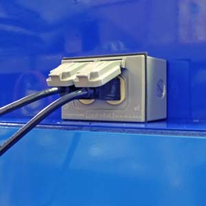 Located on the back of the GT75. Worklamp power cord also plugs in here.on back of machine. On very early machines, the CNC may be plugged into a wall-socket.
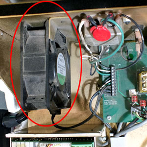 Located in CNC, on back panel.in the CNC is running. (Remove blue cover if you cannot hear the fan).
 Located on the back of the CNC control.on the back of the CNC Control.
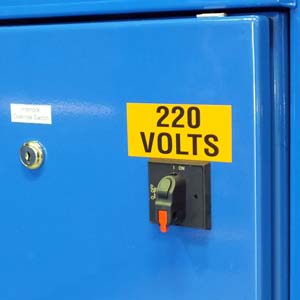 Located on left side of GT75.on spindle cabinet is ON. Also check the fuses
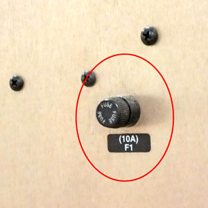
 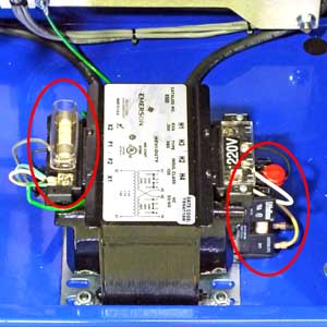 Located in spindle drive cabinet.on step-down transformer in spindle cabinet. NOTE: On GT75 machines with step-down transformer, the worklamp will light if these fuses are ok.
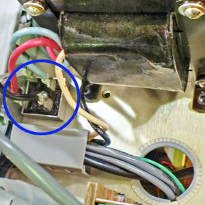 Located in CNC, on top chassis., located on CNC top chassis
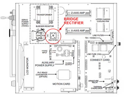 Bridge rectifier location on top chassis., is probably bad. P/N 995-15-002.
To quickly determine if it’s just the monitor, set power on, then wait a minute for the computer to boot up, then press the "Caps Lock" key and see if the "Caps Lock" light goes on. If it does, replace the Control ON bulb 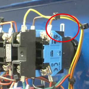
Rotate locking lever to access bulb. and click here to troubleshoot the monitor.
If the "Caps Lock" light does not come on when you press the key, do the following to check the computer power supply:
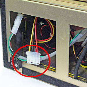 Computer power supply connector..
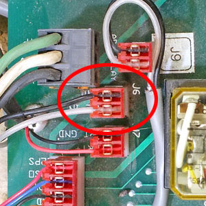 Located in CNC on connect card.on the connect card
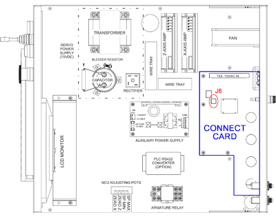 Location of J6 on connect card..Located in CNC on connect card. and the metal clips that hold the clear wire on J6.
To verify that the Control On switch is properly connected, first set control power OFF, then check the following:
 Located in CNC on connect card.on the connect card
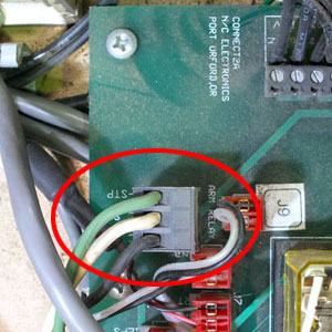
 Location of TS1 on connect card.. Located in CNC on connect card.. Verify that all three wires are securely held by the terminal screws, then plug TS1 back in.
  TS1 wires at switches.
 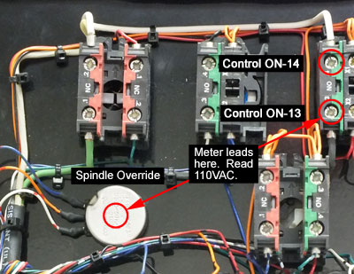 Check 110VAC at Control ON. If fuses are all good, you should measure about 110VAC.