OmniTurn   CNC Lathes Made in Oregon
 Fast... Precise... Affordable... Home Contact

The World’s Most Cost-Effective Turning Machines

Collet Closer Not Working (G4 CNC)

This page will guide you through troubleshooting collet closer issues.
If the issue is collet doesn't always open, and your machine is equipped with Dunham collet colser, the issue could be mechanical.
If the issue is M12 and M13 works but Palm Box (Operator's Station) buttons, or CL/OP toggle on control don't work, the issue could be switch contacts.
If the issue is neither switches nor M12 (or M13) work, the issue could be low voltage, or bad solenoid valve.
Scroll down to see discussion of each of these.

Mechanical Issue

If the collet intermittently doesn't open, the collet may be stuck.

If you can release the collet with a light tap on the knurled knob using a dead-blow hammer, the collet is stuck.

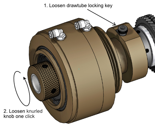
To correct this issue, loosen the drawtube locking key to disengage the drawtube, then loosen the drawtube by one 'click'.

Re-tighten the drawtube locking key.

Dunham Collet Actuator

Image of Dunham Collet Actuator

Switch Contacts

If the collet actuates properly with M12 and M13 but not with the manual collet open and close buttons, the problem may be a bad switch.

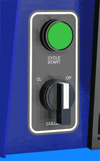
Toggle the Collet CL / OP switch on the control and verify that the collet opens and closes.
NOTE: This assumes that M12 or M13 work properly from MDI mode, and with the Palm Box (Operator's Station) Collet Open or Close push buttons.

If the CL/OP switch works consistently, press the Open and Close pushbuttons on the Palm Box (Operator's Station).
NOTE: This assumes that M12 or M13 work properly from MDI mode and with the Collet CL / OP toggle.

Collet OP/CL Switch

Image of Collet OP/CL Switch

Collet Actuator Buttons

Image of Palm Box

Low Voltage

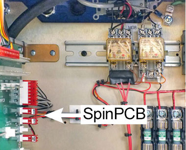
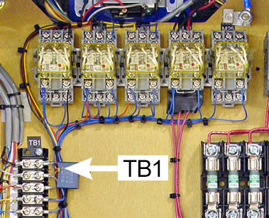
The solenoid valves on your machines are connected to either a circuit board (SpinPCB) or terminal strip (TB1) inside the spindle drive electronics cabinet, as shown in the images below.
Machines with circuit card started shipping December 2011, with GT serial number 4568PTI; control serial number 4599G4Y.

Printed Circuit Card (PWB)

Image of spindle panel with printed circuit card (PWB)

Terminal Strip (TB1

Image of spindle panel with terminal strip (TB1)

Measure the Voltage at Collet Actuator Outputs: SpinPCB

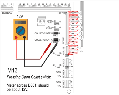
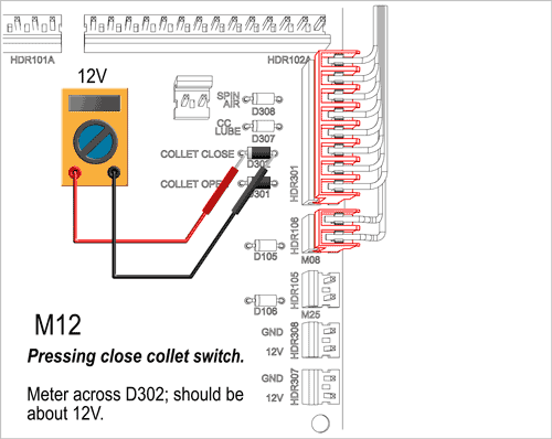
On machines with SpinPCB the solenoid valves are wired to connector HDR301.

Voltages are measured across diodes located just to the left of HDR301.

To test M13, measure voltage across diode D301. Press Open Collet switch: you should read about 12V on the meter.

To test M12, measure voltage across diode D302. Press Close Collet switch: you should read about 12V on the meter.

If the voltage is more than 10 volts at the diodes but the valve isn't operating, the problem is either in the valve itself or in the wiring to it. You can check the valve here.

If the voltage across the diode is less than 10 volts DC with the switch pressed, there might be a problem with the control or the wiring. Scroll down to Measure the 12V "Servos On" Voltage.
M13 Voltage Check PWB

Image of Voltmeter at D301

M12 Voltage Check PWB

Image of Voltmeter at D302

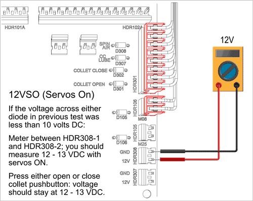
Measure the 12V "Servos On" voltage: SpinPCB

If the voltage across either diode in previous test was less than 10 volts DC:

  • Meter between HDR308-1 and HDR308-2; you should measure 12 - 13 VDC with servos ON.
  • Press either open or close collet pushbutton: voltage should stay at 12 - 13 VDC.

If the voltage at HDR308 stays at 12 - 13 VDC with either collet open or collet closed switch pressed, there may be an issue with output on the motion card in the control, or with the wiring from the motion card.

If the voltage at HDR308 doesn't stay at 12 - 13 VDC with either collet open or collet closed switch pressed, there may be an issue with the auxilliary power supply in the control, or with the wiring from aux power supply to HDR308.

"Servos On" Voltage Check PWB

Image of Voltmeter at HDR308

Measure the Voltage at Collet Actuator Outputs: TB1

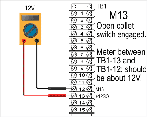
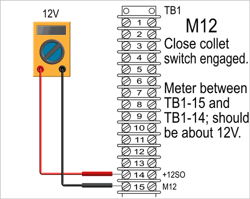
On machines with TB1 the solenoids are wired to TB1-12 (M13) and TB1-15 (M12).

Voltages are measured between screw terminals located on the vertical terminal strip TB1.

To test M13, measure voltage beween TB1-12 and TB1-13.
Press Open Collet switch: you should read about 12V on the meter.

To test M12, measure voltage between TB1-15 and TB1-14.
Press Close Collet switch: you should read about 12V on the meter.

If the voltage is more than 10 volts between those terminals, but the valve isn't operating, the problem is either in the valve itself or in the wiring to it. You can check the valve here.

If the voltage between TB1-12 and TB1-13 (or between TB1-15 and TB1-14) is less than 10 volts DC, there might be a problem with the control or the wiring. Scroll down to Measure the 12V "Servos On" Voltage.

M13 Voltage Check TB1

Image of Voltmeter at TB1

M12 Voltage Check TB1

Image of Voltmeter at TB1

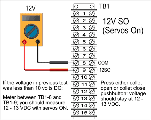
Measure the 12V "Servos On" voltage: TB1

If the voltage across either TB1-12 & TB1-13 or TB1-15 & TB1-14 in previous test was less than 10 volts DC:

  • Meter between TB1-8 & TB1-9; you should measure 12 - 13 VDC with servos ON.
  • Press either open or close collet pushbutton: voltage should stay at 12 - 13 VDC.

If the voltage between TB1-8 & TB1-9 stays at 12 - 13 VDC with either collet open or collet closed switch pressed, there may be an issue with output on the motion card in the control, or with the wiring.

If the voltage between TB1-8 & TB1-9 doesn't stay at 12 - 13 VDC, there may ben an issue with the auxilliary power supply in the control, or with the wiring from aux power supply to TB1-9.

"Servos On" Voltage Check PWB

Image of Voltmeter at 12VSO TB1

Check Solenoid Valves

Voltage across diodes (SPINPCB) or between terminals (TB1) is greater than 10VDC with either collet open or collet closed switch pressed, but the collet still doesn't accuate.

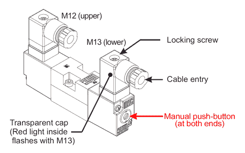
First verify that the indicator LED on the MAC valves consistently light when pressing collet open or close switch. This insures that the signal is reliably transmitted from the CNC control to the solenoid valve.

If the LEDs don’t consistently light with switches depresssed, the problem is wiring, somewhere between the circuit card (or TB1) and the solenoid.

If the LEDs consistently light, the voltage may be too low to actuate the valve, or the valve maybe stuck. Actuate the valve manually a few times then try again by pressing collet open or closed switch

Air Pack on GT

Image of Air Pack on GT

Manually Actuate the Valve

Using a ball-point pen or small allen wrench, depress the grey "bullseye" button at the bottom end of the the solenoid valve to open collet. Depress the button at the top side to close the collet.

Open and close the collet this way a few times, then try to actuate the collet using the collet open and close push buttons. If the collet actuates properly, the cause was sticky valve. Check the main regulator filter; drain the liquid if necessary.

If the collet still doesn't actuate with the pushbutton, the voltage at the solenoid may be low. Scroll down to Check Voltage at Solenoid.

Collet Actuator Solenoid

Image of MAC Double Solenoid Valve

Check Voltage at Solenoid

  1. Loosen locking screw and unplug transparent cap with cable.
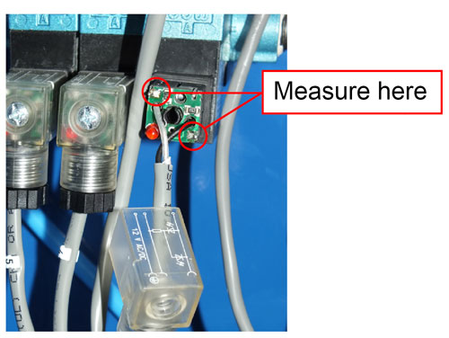
  2. Jiggle transparent cap off the plug, then slide it down the cable, away from the plug, to access connections.
  3. Replug the connector and cable onto solenoid.
  4. Press Open Collet pushbutton and measure between the two points shown; should be about 11.5VDC.
(Do this at top solenoid for Close collet issue)

If voltage is about 11.5V but valve does not actuate, replace the valve: Mac Double Solenoid Valve Only; 997-15-007; $175
If voltage is much lower, or zero, the problem is wiring, somewhere between the circuit card (or TB1) and the solenoid.

Check Voltage at Solenoid

Image of Test Points on MAC Solenoid Valve