CNC Control Switches

Operator's Station

CNC Control Switches
Operator's Station
1CR (Servos Enable relay)

M08 (Coolant On relay)

If the E-Stop switches are disengaged, and you’ve swapped 1CR with M08, but you still cannot turn on the servos, you will need a voltmeter to troubleshoot the problem.
Remove the blue cover of the CNC and locate the red header connector on the Connect Card.
Measurements are taken at the “Turn Servos On” prompt.
G3 Connect Card

First verify E-Stop switches on CNC and on Palm Box (Operator’s Station) are dis-engaged; next, swap 1CR with M08 in spindle drive cabinet.
G3 Red Header

If the 12VDC is NOT present from GND to 12SW (#2 above), there is open circuit between 12PS and 12SW. Scroll down to (A) under Continuity Testing.
If the 12VDC IS present from GND to 12SW (#2 above) but CRDY to 12SW is NOT about 11V (#3 above), and GND to CRDY is NOT about 1VDC (#4 above), either your MC2 card is not producing the CRDY signal, or the wide ribbon cable that runs from the MC2 card down in the computer up to the connect card is not plugged in all the way.
If the CRDY to 12SW is about 11V (#3 above), and GND to CRDY is about 1VDC (#4 above), but servos don't come on when Servos ON is pressed, there is an open connection in the wiring to the Servo On switch, or a bad contact on that switch.
To verify Servo On switch circuit, put black meter lead at GND and red lead at IN02; the meter should read about +12VDC. Press the Servos On button; the voltage should drop to about +1VDC:
Turn off the control, and UNPLUG IT FROM THE POWER RECEPTACLE!
(A) If the 12VDC is NOT present from GND to 12SW (#2 above), then there is open circuit between 12PS and 12SW. Refer to schematic and instructions below. The bold line, from 12PS to 12SW is the circuit you are checking.
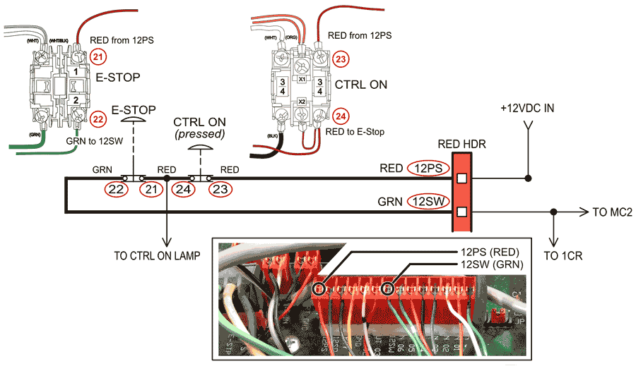
Turn off the control, and UNPLUG IT FROM THE POWER RECEPTACLE, press Ctrl On switch, dis-engage front panel E-stop, then use your continuity tester or ohm meter to check between following points:
The open circuit is wherever you didn’t get continuity
(B) If CRDY to 12SW is about 11V (#3 above) but GND to IN02 stays at about +12VDC with Servos ON pressed, there is open circuit between CRDY and IN02. Refer to schematic and instructions below. The bold line, from IN02 to CRDY is the circuit you are checking.
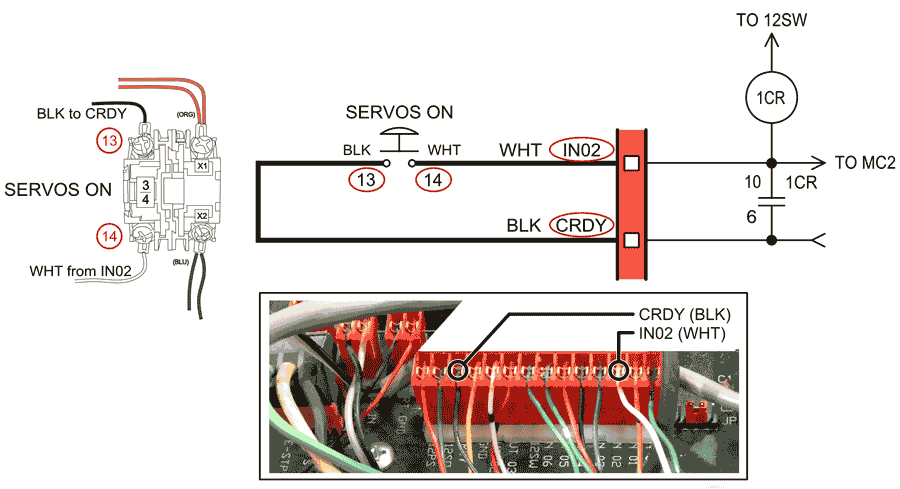
Turn off the control, and UNPLUG IT FROM THE POWER RECEPTACLE!
Use your continuity tester or ohm meter to check between the following points:
The open circuit is wherever you didn’t get continuity.
Turn on the control and get to the "Please turn on servos" prompt. (Since you're here, press the Servos On pushbutton, just to see if the issue 'fixed itself').
If the servos don't come on, remove the blue cover and look at the exposed printed circuit card. This is the backside of the MC2 card.
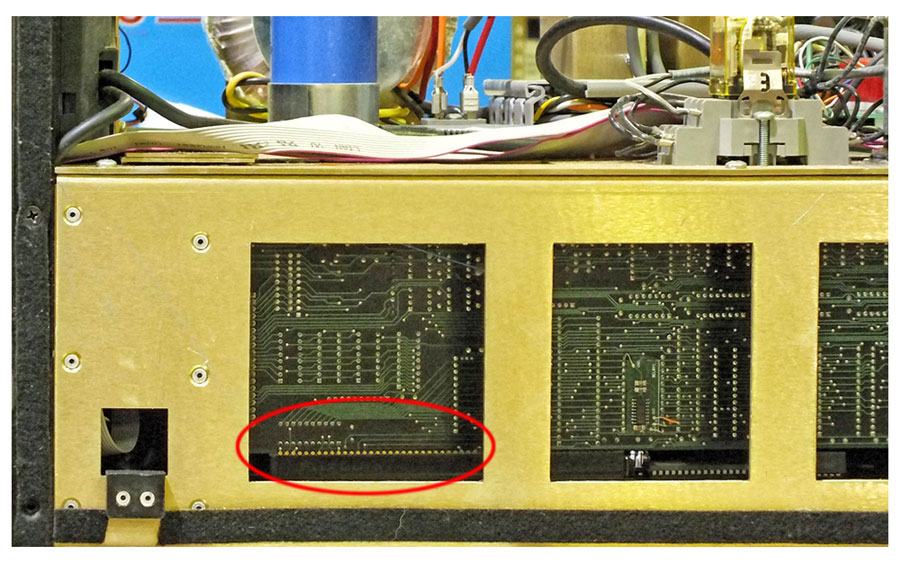
At “Turn Servos On” prompt:
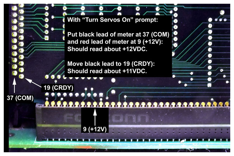
To access the MC2 card you must remove the top chassis from the control. Disassembly instructions are available here.
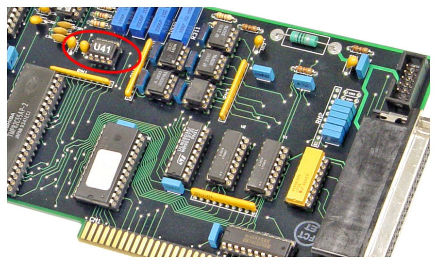
Remove U41 by slipping a small screwdriver under one end of the IC, then the other, alternately lifting each end of the IC by a small amount so as not to bend the leads.
Replacement U41 (SN75452BP) is available at DigiKey.
When installing the new one, be sure you orient it correctly. Pin 1, which is marked by either a dot or a half-circle depression in the plastic case of the chip, goes to the left (away from the 37-pin connector). Be sure all the pins on the chip are well aligned with the socket when you push it in, making sure that no pins get bent under the body of the chip. It's easy to bend them but hard to straighten them w/o breaking them off.