Back to plane-switching commands
The ZC mode is started with the command (~PLZC).
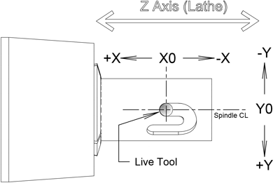
Before entering this command the live tool must be located on the negative X side of the part, with its spindle centerline parallel to the lathe’s X axis.
On entry, the tool is centered at X0 and Y0 position in the virtual milling machine, so before switching planes you need to locate the Z and C axes to the location you want to be X0,Y0 on the part surface. NOTE: You must accommodate the tool diameter, and program accordingly.
X positive motion is to the right (toward the spindle face) as viewed from the live spindle’s point of view, and Y positive motion is up from the live tool’s point of view.
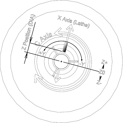
Because most lathe programming refers to radial positions as diameters, Z dimensions are given as the diameter of the cylinder the tool tip would touch. The virtual mill’s Z axis is set to the X position prior to the plane switch, but the sign is inverted, so that a positive Z move moves the tool tip away from the part center.
For example, in this code:
m19
T11(call up live tool)
x-1z.5 (tool is at a 1inch diameter on -X side of part)
z-.2
(~plzc) plane switch mill position is x0,y0,z1
(f5z.85) tool tip moves in to cut at a diameter of .85
Note that the z.85 command moves the tool tip in toward the center of the part.
C-Axis ZC Plane Switching Examples
The following examples were cut in a 7/8" delrin bar with a 1/16" end mill.
Note:if you copy these programs, do not include comments in the plane switched section. Nothing is allowed in the plane-switched program except the program statements described above.
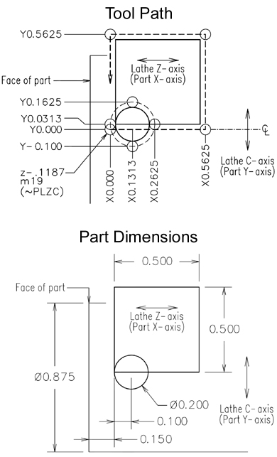
Engrave a 1/2" square with a .2" diameter circle in the lower left corner.
m27
t11
x-1z1
z-.1187 (x0y0 on virtual mill puts edge of square at Z-0.150)
m19 (enable C axis)
(~PLZC) start ZC mode (f10)
(z.85) feed tool into workpiece
(d.875) set diameter for Y axis scaling
(x.5625) move toward spindle face .5+ tool diameter
(y.5625) up .5625
(x0) back to start in X
(y0) then Y
(y.0313) start point for circle
(g02x.1313y.1625i.1313j.0313) do a cw circle in 4 segments centered at x.1313,y.0313 (g02x.2625y.0313i.1313j.0313)
(g02x.1313y-.1i.1313j.0313)
(g02x0y.0313i.1313j.0313)
(z1) withdraw tool
(end) cancel plane-switch mode
x-1
z1
m30
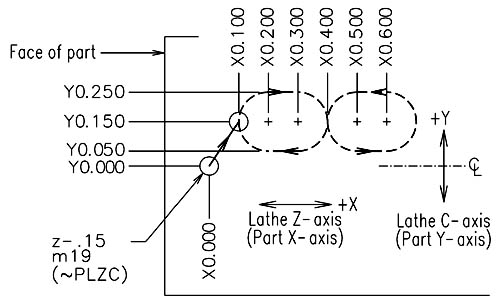
Engrave a figure-8 pattern consisting of 2 oval racetrack" patterns joined together.
 m27 (turn on live tool)
t11
x-1z1
z-.15 (x0y0 on virtual mill)
m19 (turn on C axis)
(~PLZC)
start CZ mode
(d.875)
set Y axis scaling to 7/8" diameter
(x.1y.15f20)
move to starting X-Y position
(z.775f10)
plunge tool in to a depth of .05"
(g02x.2y.25i.2j.15)
cw 90 deg arc moving right .1",up .1" centered at x.2, y.15
(x.3)
straightaway to the right .1"
(g02x.4y.15i.3j.15)
another 90 deg. cw arc
(g03x.5y.05i.5j.15)
now a ccw 90 deg arc
(x.6)
bottom straight on right-hand oval
(g03x.6y.25i.6j.15)
ccw 180 deg arc
(x.5)
top straight on right oval
(g03x.4y.15i.5j.15)
ccw arc back to start of right oval
(g02x.3y.05i.3j.15)
cw arc to bottom straightaway of left oval
(x.2)
bottom straight
(g02x.1y.15i.2j.15)
cw arc back to start point
(z1)
withdraw cutter
(end)
cancel plane-switch
x-1
z1
m30
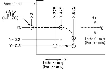
Cut a J-slot like those found on electrical connector housings.
m27 (turn on live tool)
t11
x-1z1
z.075 (x0y0 on virtual mill)
m19 (turn on C axis)
(~PLZC) start ZC mode
(d.875) set Y axis scaling to 7/8" diameter
(z.775f10) move in to a cut depth of .05"
(x.475) cut straight side of J
(g02x.675y-.2i.475j-.2) right turn at end of long side
(y-.3) short straight segment
(x.375) move back in x to create detent notch
(z1) withdraw tool
(end) cancel plane switch
x-1
z1
m30